Protected Mode Basics
by
Robert Collins
I remember when I was first learning protected mode. I had barely taught myself assembly language, and I got this crazy idea that I wanted to teach myself protected mode. I went out and purchased an 80286 assembly language book that included some protected mode examples, and I was off to learn. Within a few hours, I realized that the book I had purchased didn't have any usable examples, since the examples in the book were intended to be programmed in EPROM CHIPS. So I hit the bulletin boards in search of something I could use as a guiding example.
The only example I found was so poorly documented and convoluted with task switching that even now, many years later, I haven't figured it out. So with my IBM Technical Reference Manual and my 80286 book, I sat down and tried to figure out protected mode. After spending forty hours in three days of trying, I finally copied some source code out of the IBM Technical Reference Manual, and I was able to enter protected mode and then return to DOS.
Since that time, I have learned much about protected mode and how the CPU handles it internally. I discovered that the CPU has a set of hidden registers that are inaccessible to applications. I also learned how these registers get loaded, their role in memory management, and most importantly, their exact contents. Even though these registers are inaccessible, understanding the role they play in memory management can be applied to application's programming. Applying this knowledge to programming can result in applications that use less data, less code, and execute faster.
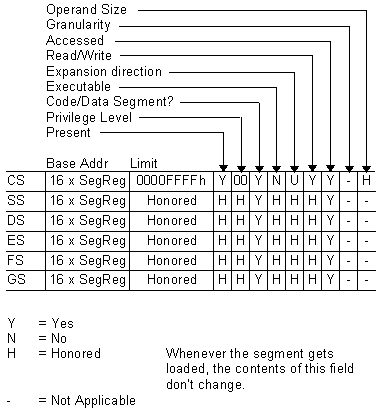
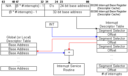
PROTECTED MODE BASICSFrom an applications' point of view, protected mode and real mode aren't that different. Both use memory segmentation, interrupts, and device drivers to handle the hardware. But there are subtle differences that make porting DOS applications to protected mode non-trivial. In real mode, memory segmentation is handled automatically through the use of an internal mechanism, in conjunction with segment registers. The contents of these segment registers form part of the physical address that the CPU presents on the address bus (see figure 1a). The physical address is generated by multiplying the segment register by 16, then adding a 16-bit offset. Using 16-bit offsets implicitly limits the CPU to 64k segment sizes. Some programmers have programmed around this 64k segment size limitation by incrementing the contents of the segment registers. Their programs can point to 64k segments in 16-byte increments. Any program using this technique in protected mode would generate an exception (CPU-generated interrupt) -- since segment registers aren't used in the same manner. In protected mode, memory segmentation is defined by a set of tables (called descriptor tables) and the segment registers contain pointers into these tables. Each table entry is 8-bytes wide; therefore the values contained in the segment registers are defined in multiples of 8 (08h, 10h, 18h, etc.). The lower three bits of the segment register are defined, but for simplicity's sake, let's say that any program that loads a segment register with a value that isn't a multiple of 8 will generate a protection error. There are two types of tables used to define memory segmentation: the Global Descriptor Table (GDT), and the Local Descriptor Table (LDT). The GDT contains segmentation information that all applications can access. The LDT contains segmentation information specific to a task or program. As previously mentioned, segment registers don't form part of the physical address in protected mode, but instead are used as pointers to table entries in the GDT or LDT (see figure 1b). Each time a segment register is loaded, the base address is fetched from the table entry and stored in an internal, programer-invisible, register called the "segment descriptor cache." The physical address presented on the CPU address bus is formed by adding the 16 or 32-bit offset to the base address in the descriptor cache. Another major concern for porting real-mode applications to protected mode is the use of interrupts. In real mode, double-word pointers to interrupt routines lie at physical address 0 ('386 specific: unless the IDTR has been changed).Figure 4a illustrates interrupt service addressing in real mode. When an interrupt is called or generated, the CPU looks up the address of the Interrupt Service Routine (ISR) in this interrupt vector table. After the CPU pushes the flags on the stack, it performs a far call to the address in the table. The information pushed on the stack is the same for software, hardware, or CPU generated interrupts. In protected mode, the information pushed on the stack can vary, as can the base address of the interrupt vector table and the size of the interrupt table. The interrupt vector look up mechanism is also quite different from its real-mode counterpart. Figure 4b shows how interrupts are called from protected mode. After an interrupt is generated, the CPU compares the interrupt number (x8) against the size of the IDT -- stored in the interrupt descriptor cache register. If the INT# x 8 doesn't exceed the IDT size, then the interrupt is considered invokable, and the IDT base address is fetched from the descriptor cache; then the ISR's protected mode address is fetched from the IDT. The ISR's address is not a physical address but a protected mode, segmented address. Using the segment selector specified in the IDT, the CPU must perform the same limit-checking process again on the GDT to calculate the physical address of the ISR. Once the physical address is calculated, the CPU pushes the FLAGS, SEGMENT (selector), OFFSET, and possibly an ERROR CODE on the stack before branching to the ISR. ISRs for software and hardware interrupts needn't be any different from their real-mode counterparts, but ISRs to service CPU generated interrupts and faults must be different. The CPU generates three categories of
interrupts: traps, faults, and aborts. The stack
image varies from category to category, as an
error code may, or may not, be pushed on the
stack. Traps never push an error code; faults
usually do; and aborts always do. Traps are
similar to and include software interrupts. This
type of interrupt is appropriately named, as the
CPU is "trapping" the occurrence of an
event. The CPU doesn't know the event occurred
until after the fact; thus it must trap the event
before signalling the interrupt. Therefore, the
return address of these ISR's point to
instruction following the occurrence of the
event. Traps include division by 0, data
breakpoints, and INT03. Faults occur because
something went wrong -- something that should be
fixed. The CPU knows instantly that something is
wrong and signals the interrupt-generating
mechanism. The primary purpose of this type of
ISR, is to correct the problem and restart the
program exactly where it left off. For this
reason, the return address of the ISR points to
the faulting instruction -- thus making the fault
restartable. Aborts are the most severe type of
interrupt and are considered non-restartable. An
error code is pushed on the stack, but will
always be 0. The CPU's stack segment, and state
machines, may be in an I used to wonder why the BIOS can't be used in protected mode. At that time, I thought it would be easy to write mode-independent code: just don't do any FAR JUMPs, or FAR CALLS. But it's not as simple as following these conventions. In addition to avoiding the use of far jumps and calls, the ISR must remove any error code pushed on the stack. This is where the impossibilities begin. Since the error code is placed on the stack only in protected mode, we need to detect whether or not we are in protected mode before the error code is removed. To determine this, we need access to the machine status work (MSW), or the system register CR0. Accessing the MSW can be done in any priviledge level, but accessing CR0 can only be done at the highest privilege level -- level 0. If the user program is executing at any level less than 0, then we might not be able to access these registers. It can be done through the use of a special call gate that allows us to switch privilege levels before calling the ISR. This isn't needed if we use the SMSW instruction. But even with that problem solved, let's suppose the program left a real-mode value in any one of the segment registers. If the ISR pushes and subsequently pops any of these registers, the pop will cause the CPU to look for a selector in the GDT, or LDT. More than likely, using a real-mode value will cause a protection error. Therefore, using the BIOS in protected mode is nearly impossible. If there were a defined set of rules (a standard) that all programmers and operating systems followed, it could be done. |
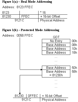
Figure 4(a) --
Interrupt service addressing in Real Mode Fig 4(b) Interrupt
service addressing in Protected Mode
|
||||||||||||||||||||||||||||||||||||||||||||||||||||||||||||||||||||||||||||||||||||||||||||||||||||||||||||||||||||||||||||||||||||||||||||

ENTERING PROTECTED MODE
Our goal is to enter protected mode, and leave protected mode and return to DOS. The '286 has no internal mechanism to exit protected mode: once you are in protected mode, you are there to stay. IBM recognized this, and implemented a hardware solution that would take the '286 out of protected mode by resetting the CPU. Since the power-on state of the '286 is real mode, simply resetting the CPU will return to real mode. But this introduces a slight problem, as the CPU won't continue executing where it left off. At reset, the CPU starts executing at the top of memory, in the BIOS. Without a protocol to tell the BIOS that we reset the CPU for the purpose of exiting protected mode, the BIOS would have no way to return control back to the user program. IBM implemented a very simple protocol by writing a code to CMOS RAM (CMOS) where the BIOS can check this code and decide what to do. Immediately after the BIOS starts executing from the reset vector, it checks this code in CMOS to determine if the CPU was reset for the purpose of exiting protected mode. Depending on the code in CMOS, the BIOS can return control back to the user program and continue executing.
Resetting the CPU isn't without its ramifications; all the CPU registers are destroyed, and the interrupt mask in the Programmable Interrupt Controller (PIC) is sometimes re-programmed by the BIOS (depending on the shutdown type). Therefore, it is the program's responsibility to save the PIC mask, stack pointer, and return address before entering protected mode. The PIC mask and stack pointer must be stored in the user's data segment, but the return address must be stored at a fixed location defined in the BIOS data segment -- at 40:67h.
Next, we set the code in CMOS that tells BIOS we will exit protected mode and return to the user's program. This is simply done by writing a value to the two CMOS I/O ports. After the CPU gets reset, and BIOS checks the CMOS code, BIOS will clear the CMOS code, so subsequent resets won't cause unexpected results. After setting the code in CMOS, the program must build the GDT. (See the appropriate Intel programmer's reference manual for a description of the GDT.) The limit, and access rights may be filled in by the compiler, as these values are static. But the base addresses of each segment aren't known until run-time; therefore the program must fill them in the GDT. Our program will build a GDT containing the code, data, and stack segments addressed by our program. One last GDT entry will point to 1M for illustrative purposes.
Accessing memory at 1M isn't as simple as creating a GDT entry and using it. The 8086 has the potential to address 64k (minus 16 bytes) beyond the maximum addressability of 1M -- all it lacks is a 21st address line. The 8086 only has 20 address lines (A00..A19), and any attempt to address beyond 1M will wrap around to 0 because of the absence of A20. The '286 has 24 bits of addressability (A00..A23) and doesn't behave like the 8086 in this respect. Any attempt to address beyond 1M (FFFF:0010 - FFFF:FFFF) will happily assert A20, and not wrap back to 0. Any program that relies on the memory wrapping "feature" of the 8086, will fail to run properly. As a solution to this compatibility problem, IBM decided to AND the A20 output of the CPU with a programmable output pin on some chip in the computer. The output of the AND gate is connected to the address bus, thus propogating or not, A20. Based on the input from the CPU A20, ANDed with an externally programmable source, address bus A20 gets asserted. The keyboard controller was chosen as this programmable source because it contained some available pins that can be held high, low, or toggled under program control. When the output of this pin is programmed to be high, the output of the AND gate is high when the CPU asserts A20. When the output is low,A20 is always low on the address bus -- regardless of the state of the CPU A20. Thus by inhibiting A20 from being asserted on the address bus, '286- class machines can emulate the memory wrapping attributes of their 8086 predecessors.
Notice that only A20 is gated to the address bus. Therefore, without enabling the input to the A20 gate, the CPU can address every even megabyte of memory as follows: 0-1M, 2-3M, 4-5M, etc. In fact, duplicates of these memory blocks appear at 1-2M, 3-4M, 5-6M, etc. as a result of holding A20 low on the address bus. To enable the full 24-bits of addressability, a command must be sent to the keyboard controller (KBC). The KBC will enable the output on its pin to high, as input to the A20 gate. Once this is done, memory will no longer wrap, and we can address the full 16M of memory on the '286, or all 4G on 80386-class machines. All that remains in order to enter protected mode is changing the CPU state to protected mode and jumping to clear the prefetch queue (not necessary on the Pentium).
The following table summarizes the steps required to enter (with the intention of leaving) protected mode on the '286:
- Save the 8259 PIC mask in the program data segment
- Save SS:SP in the program data segment
- Save the return address from protected mode at 40:67
- Set the shutdown code in CMOS to tell BIOS that upon reset we will be returning to our program
- Build the GDT
- Enable A20 on the address bus
- Enable protected mode in the CPU machine status word (MSW)
- JUMP to clear the prefetch queue
Steps 1-6 can be done in any order.
The minimum number of steps required to enter protected mode on the '386 and '486 are far fewer, as the '386 can exit protected mode without resetting the CPU. For compatibility purposes, all '386 BIOS's will recognize the CPU shutdown protocol defined on '286-class machines, but following this protocol isn't necessary. To exit protected mode on a '386, the program simply clears a bit in a CPU control register. There is no need to save the PIC mask, SS:SP, a return address, or set a CMOS code. The requisite steps for entering protected mode on a '386 simply become:
- Build the GDT
- Enable A20 on the address bus
- Enable protected mode in the CPU control register (CR0, or MSW)
- JUMP to clear the prefetch queue
Of these requisite steps, building the GDT is the only step that may differ. In the '386 the base address is expanded to 32-bits, the limit is expanded to 20-bits, and two more control attribute bits are present. Listing 1 lists all the auxiliary subroutines to enter protected mode.
EXITING PROTECTED MODE
Like entering protected mode, exiting it differs from the '286 to 80386-class machines. The '386 simply clears a bit in the CPU control register CR0, while the '286 must reset the CPU. Resetting the CPU isn't without its costs, as many hundred -- if not thousands -- of clock cycles pass in the time it takes to reset the CPU and return control back to the use program. The original method employed by IBM used the keyboard controller by connecting another output pin to the CPU RESET line. By issuing the proper command, the KBC would toggle the RESET line on the CPU. This method works, but it is very slow. Many new generation '286 chip sets have a "FAST RESET" feature. These chip sets toggle the RESET line by simply writing to an I/O port. When available, FAST RESET is the preferred method. But there is a third, obscure, but efficient method for resetting the CPU without using the KBC or FAST RESET. This method is elegant, faster than using the KBC, and works on the '386 WITHOUT resetting the CPU! It is truly the most elegant, comprehensive way to exit protected mode, since it works on both the '286, and '386 -- in the most efficient way possible for each CPU. Listing 2 provides the code necessary to use the KBC and this elegant technique.
Using the KBC to reset the CPU is a straightforward technique, but in order to understand the elegant technique, some explanation is required. Recall that in our discussion of interrupts, the CPU checks the interrupt number (x8) against the limit field in the interrupt descriptor cache register (IDTR). If this test passes, then the next phase of interrupt processing begins. But if the test fails, then the CPU generates a DOUBLE FAULT (INT08). For example, let us suppose the limit field in the IDTR=80h: our IDT will service 16 interrupts, 00-15. If interrupt 16 or above was generated, the CPU would DOUBLE FAULT because a fault was generated at the inception of the interrupt calling sequence. Now, suppose the limit field in the IDTR=0, thus inhibiting all interrupts from being serviced. Any interrupt generation would cause the DOUBLE FAULT. But the DOUBLE FAULT itself would cause a fault, due to the limit being less than 40h. This ultimately would cause a TRIPLE FAULT, and the CPU would enter a shutdown cycle. The shutdown cycle doesn't reset the CPU, as a shutdown cycle is considered a BUS cycle. External hardware is attached to the CPU to recognize the shutdown cycle. When a shutdown cycle is observed, the external hardware toggles the RESET input of the CPU. Therefore, all we need to do to cause the RESET is set the IDTR.LIMIT=0, then generate an interrupt. For elegance, we don't just INT the CPU, we generate an invalid opcode. Our opcode is a carefully chosen opcode that doesn't exist on the '286, but does exist on the '386. The elegance in the algorithm is in the opcode chosen for this purpose: MOV CR0,EAX. This will generate the desired invalid opcode exception on the '286, but is the first instruction in a sequence to exit protected mode on the '386. Thus the '286 gets RESET, and the '386 falls through and exits protected mode gracefully.
Exiting protected mode on the '286, and '386 closely resemble reversing the steps for entering protected mode. On the '286, you must:
- Reset the CPU to get into real mode
- Load the segment registers with real mode compatible values
- Restore SS:SP
- Inhibit A20 from the address bus (gate A20 off)
- Restore the PIC masks
And on the '386, the steps are simply:
- Load the segment registers with real-mode compatible values
- Reset the Protection Enable (PE) bit in CR0
- Load the segment registers with real mode values
- Inhibit A20 from the address bus (gate A20 off)
(Listing 3 includes the subroutines needed to restore the machine state after exiting protected mode).
Notice that exiting protected mode on the '386 requires loading the segment registers twice. The segment registers are loaded the first time to assure that real-mode compatible values are stored in the hidden descriptor cache registers -- as the descriptor cache registers "honor" the access attributes, and segment size limit, from protected mode, even when loaded in real mode. The segment registers are loaded the second time to define them with real-mode segment values.
Now that we have all the tools and theory necessary to enter and exit protected mode, we can apply this knowledge to write a program that enters protected mode, moves a block of data from extended memory, and exits protected mode -- returning to DOS. Listing 4 shows a program that consists of these basic steps and can be used to move a 1k block of data from 1M to our program's data segment.
CONCLUSION
Applications programming for real mode and protected mode aren't that different. Both modes use memory segmentation, interrupts, and device drivers to support the hardware. Whether in real mode or protected mode, a set of user-inaccessible registers -- called descriptor cache registers -- play a major role in memory segmentation and memory management. The descriptor cache registers contain information defining the segment base address, segment size limit, and segment access attributes, and are used for all memory references -- regardless of the values in the segment registers.
Entering and exiting protected mode requires nothing more than following the mechanics necessary for the proper mode transition: entering protected mode requires saving the machine state that needs to be restored upon exiting protected mode. The mechanics of entering real mode depend on the type of the CPU: the '286 requires a reset to enter real mode, and the '386 can enter real mode under program control. By applying our knowledge of how the CPU internally operates, we can write source code that exits protected mode in the manner best suited, and most elegant, for the given CPU.
View source code for PMBASICS:
http://www.rcollins.org/ftp/source/pmbasics/tspec_a1.asm
http://www.rcollins.org/ftp/source/pmbasics/tspec_a1.l1
http://www.rcollins.org/ftp/source/pmbasics/tspec_a1.l2
http://www.rcollins.org/ftp/source/pmbasics/tspec_a1.l3
http://www.rcollins.org/ftp/source/pmbasics/tspec_a1.l4
Download entire source code archive:
http://www.rcollins.org/ftp/dloads/pmbasics.zip
Back to Books and Articles home page